Our company's heat treatment carburizing production line was introduced from Germany in 1995. The production line is double-row push rod type, the quenching oil tank is closed type, and the oil tank temperature has two-way temperature control. When the temperature is raised, it is realized by a plug-in electric heater. When the temperature is lowered, the oil is sucked into the tube plate heat exchanger to cool (see Fig. 1), and the quenching cooling medium is tap water.
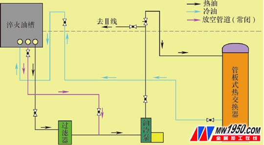
Figure 1 Oil tank cooling system
1. There is a problem with the heat exchange system
Both the heat exchanger and the oil cooling pump are installed in the pit between the main furnace and the tempering furnace. The depth of the pit is 2800mm, the layout of the pipeline is compact, the maintenance space inside the pit is small, and the environment in the pit when the equipment is running The temperature is up to 60 ° C, and the working conditions are relatively bad.
The heat exchanger in this system has a long service life and rarely fails in one service period (3 months), but oil cooling pumps often stop the line maintenance due to bearing damage and mechanical seal damage, due to the narrow space inside the pit, the environment The temperature is high, the maintenance work is progressing slowly, and the average stop line is 1~2h, which has certain impact on quality and production. At the same time, because the work in the pit belongs to a confined space operation, the exhaust gas and carbon dioxide overflowing in the furnace are easily enriched in the pit, and there is a risk of suffocation and heat stroke.
Based on the above factors, the existing heat exchange system urgently needs to be modified to eliminate the impact of the stop line caused by the oil cooling pump failure, reduce the labor intensity of maintenance personnel, and eliminate the risk of confined space operations.
2. Reform plan
As mentioned above, because the heat exchanger is a tube sheet structure, the design takes into account the characteristics of our company's water source. The seawater corrosion resistant 316L stainless steel can basically meet the full cycle use without leakage and oil-water mixing failure, so it is not us. Focus on the focus. The focus of our efforts is to try to raise the oil cooling pump from the pit to the ground above, and at the same time, through the bypass design, to achieve non-stop maintenance during the failure, thus eliminating the safety hazards of personnel maintenance and equipment operation.
The pump is a horizontal centrifugal pipeline pump with a head of 90m and a flow rate of 740m3/h. It has no self-priming function, so it is placed in the low position of the pit, that is, lower than the bottom of the oil tank to achieve automatic suction and discharge, if it is simply from the pit. Lifting to the ground above installation may result in slower cooling due to reduced flow, or even automatic control failure due to lack of fluid.
Under normal circumstances, if the centrifugal pipeline pump is to be automatically and repeatedly started, it is usually installed with a bottom valve or a low position. However, the oil tank is used to ensure that the hot oil during quenching is cooled in time, and the oil suction port is arranged upward in the liquid level. Therefore, it is impossible to install the bottom valve, which is why the original design installed the oil pump in the low position.
3. Cooling system parameters layout parameters
The center line of the oil cooling pump is located 132mm above the bottom of the pit; the bottom of the pit is -2800mm relative to the ground, the centerline of the current oil-cooled pump is -2668mm relative to the ground; the suction port is 390mm above the ground.
Therefore, the height difference between the suction port and the oil cooling pump center line is 390 + 2668 = 3058 mm.
Consider the parameters for lifting the oil cooling pump to the ground for installation: the center line of the oil cooling pump is 132mm above the ground; the suction port is 390mm above the ground; the height difference between the suction port and the center line of the oil cooling pump is 158mm.
At the same time, it is considered that the oil level should be maintained above 490 to 590 mm above the ground during operation, so the height difference between the suction port and the oil cooling pump center line on the ground installation is 258-358 mm, and the pump can be installed above the ground.
4. Specific plan
For the sake of safety, we will not break the original system. We will cut off the vent pipe of the oil cooling pump connected to the bottom of the oil tank to form a normally closed state. Use the interface of the oil cooling pump front oil venting pipe to lead a vertical pipe and connect it to the ground. In addition, an oil cooling pump is installed, the oil outlet is inserted into the original pipeline, and the bypass system is arranged. The motor lead of the new pump is manually switched in the electrical cabinet by installing a circuit breaker. The switching circuit breaker and the associated valve opening and closing are used to control the switching of the two pumps.
However, the parameters such as NPSH and suction stroke of the pump are not provided in the manual. The relevant calculations cannot be carried out. In combination with experience, we are worried that due to the reduction of the height difference and the excessive pump capacity, it is possible to start and stop during the pulse control. If there is a mismatch between the discharge and the suction volume, there will be a cavity between the pump body and the riser. Repeated accumulation may cause damage to the pump. For this reason, we install a stainless steel check valve on the riser below the oil groove, and reverse the cut-off. As the bottom valve acts, when the pump stops, the residual oil in the transverse pipe will be added to the riser to ensure that the impeller of the pump is always immersed in the oil, thus achieving repeated start and stop (see Figure 2).
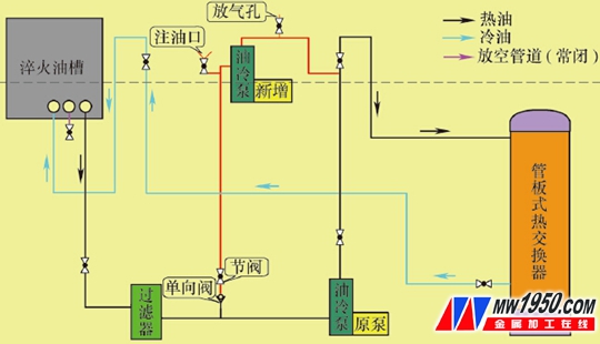
figure 2
In the process of pipeline reconstruction, considering that there is no oil in the first starting pipe, the gas resistance needs to be eliminated after starting, so the oil filling port and the gas discharging port are installed in advance, and in order to completely recover the residual oil in the heat exchanger when the heat exchanger is replaced, The oil drain valve is installed at the lowest position of the pipeline, thus achieving no leakage or waste in the maintenance process.
After the system transformation is completed, the new pump is successfully started once by oiling, deflation, switching, etc., and the cooling capacity is roughly equivalent to that of the original low-position pump, thus achieving success.
5 Conclusion
After the operation observation for about half a year, another production line was also reconstructed on this basis. Both pumps were arranged above the ground, and the switching valves were all arranged above the ground, completely eliminating the pits under running. operation.
This transformation includes design, implementation, operation observation, and conclusion. It lasted for nearly one year. The final effect shows that the transformation is relatively successful. Through the transformation, we obtained: when the pump fails, it can realize non-stop maintenance by switching; Risks such as suffocation and heat stroke may occur; the oil drain valve is added to recover the residual oil during heat exchanger maintenance; in the future, when the equipment is selected, the layout of the groundless pit can be discussed with reference to the transformation process.
About the Author:
Ren Guihu, Senior Engineer, Director of Heat Treatment Division, Internal Combustion Engine Manufacturing Branch of Tianjin FAW Xiali Automobile Co., Ltd.;
Xiao Shengjun, head of the heat treatment department of Tianjin FAW Xiali Automobile Co., Ltd.
We can produce the Boiler Pipe accordng to the EN10216 standard, such as the 10CrMo5-5 steel pipe, 10CrMo9-10 steel pipe, 13CrMo4-5 steel pipe, 15NiCuMoNb5-6-4 steel pipe, X10CrMoVNb9-1
steel pipe and X10CrWMoVNb9-2 steel pipe. Yangzhou Chengde have been sold about 700000 MT boiler pipe to the world in recent 10 years and we share the 70% of export boiler pipe in china.
At Chengde, we take quality seriously. This
philosophy carries through every aspect of our operation. That is why we
maintain a fully documented/fully certified Quality Management System which
complies with the requirements of ISO 9001. This quality system encompasses
every phase of our business. Chengde has established its complete quality
system as per ISO 9001 since 2006 and upgrade to ISO9001 :2008 at a later
stage.
Our commitment to the highest industry
standards in customer satisfaction remains our primary purpose with an emphasis
on continual improvement in both production quality and support service. Chengde
rises above the competition in delivering to you a quality/fully certified
product on schedule.
In the year of 2015, we win the first prize of National Science and Technology Progress Award by the program of [The innovative research & development, and application of steel pipes used in 600 ℃ Ultra-super critical coal power generation unit".
EN 10216 Boiler Pipe
Boiler Tube,En10216 Boiler Pipe,10Crmo5 5 Pipe,15Nicumonb5 6 4 Pipe
YANGZHOU CHENGDE STEEL PIPE CO.,LTD , https://www.chengdepipe.com