Research on NC Finishing Process of Inner and Outer Surface of Evaporator Elliptical Upper Head
The one-million-kilowatt nuclear island steam generator is a critical pressure vessel, designed to withstand high-pressure water at 15.4MPa during operation. As a first-grade safety component, uneven wall thickness can lead to uneven stress distribution, increasing the risk of hidden accidents. This paper focuses on the challenge of achieving consistent wall thickness across both inner and outer surfaces of the elliptical upper section.
**First, Analysis of Part Geometry and Accuracy Requirements**
The part features a top-and-bottom structure, with the upper section combining cylindrical and conical surfaces, and the lower section resembling a spherical shape. The internal surface has an elliptical pattern, while the external surface connects to an R125mm arc. The minimum required wall thickness is 98 mm (see Figure 1).
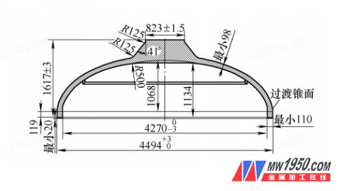
*Figure 1: Upper head*
The overall size tolerance is 3mm, with a surface roughness of Ra=3.2 μm, which aligns with the economic accuracy of CNC machine tools. However, maintaining equal wall thickness on the spherical surface presents a unique challenge. According to GB/T1804-2000, the linear dimension limit deviation is ±0.3mm. Therefore, the wall thickness must remain within ±0.3mm variation, with a total tolerance of 0.6mm. This makes the control of wall thickness accuracy a key manufacturing challenge.
**Second, Main Error Items and Control Measures in the Process System**
Achieving the required geometric accuracy and tolerances for large, complex-shaped parts is a challenging task. Several factors affect the wall thickness tolerance, including tool system errors, machining process errors, and mathematical model inaccuracies.
**1. Impact of Tool System Errors on Surface Thickness Accuracy**
This part is a rotational component, suitable for vertical CNC lathes with a rotary table. The main sources of error include the precision of the rotary table, the vertical motion trajectory of the tool holder, and the geometric positioning accuracy. Other factors include the rigidity of the tooling system and thermal deformation due to cutting heat. These errors impact the contour accuracy of inner and outer curved surfaces, reducing the available tolerance space. The target is to reduce the integrated error to T/5, or 0.12mm, with a deviation of ±0.06mm.
To achieve this, adjustments are made to the worktable rotation accuracy (0.05mm/360°), tool holder verticality (0.03mm/1000mm), and positioning accuracy (0.015mm/1000mm). Thermal management is also implemented to minimize heat accumulation. By optimizing these parameters, the system stiffness is improved, and the error is controlled effectively.
**2. Influence of Machining Process and Method on Surface Thickness Accuracy**
The CNC machining process involves precise alignment between different stations. For large parts, finishing the profiled body is particularly challenging due to potential misalignment of the positioning reference. Two working stations are used: the first ensures good positioning stability, while the second may suffer from poor stability due to a high center of gravity and limited contact area.
The error from this process is non-principal, meaning it can be reduced by selecting appropriate positioning references, controlling degrees of freedom, and optimizing cutting parameters. The target is to limit the error to T/4, or 0.15mm, with a deviation of ±0.075mm. Proper clamping and force application are essential to avoid repositioning issues that could affect the final result.
**3. Mathematical Model of NC Machining and Its Impact on Surface Thickness**
A mathematical model is used to define the inner and outer surfaces. Assuming a constant wall thickness C, the outer ellipse can be modeled as Y = (B/A)√(A² - X²), where A = a + C and B = b + C. However, this approach leads to inconsistencies in ellipticity, resulting in uneven wall thickness. To address this, a spline curve is used to ensure equal thickness across the entire surface.
By increasing the order of the spline curve from third-order to 25th-order, the density of points is significantly increased, improving contour accuracy and ensuring uniform wall thickness (see Figures 8 and 9).
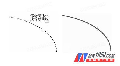
*Figure 8: Third-order spline curve*

*Figure 9: High-order sub-interpolation spline curve*
**Third, Conclusion**
1. Controlling tool system errors, machining process errors, and numerical control model inaccuracies is crucial for ensuring the quality and stability of the elliptical head. While some errors are inherent, they can be managed through proper design and adjustment.
2. Using high-order spline curves and dense point insertion in the mathematical model helps reduce precision errors, leading to more accurate and consistent wall thickness.
3. This process has been successfully applied in the production of the CPR1000 evaporator in China, with six steam generators manufactured locally. The thickness precision and stability meet technical standards, with a deviation of less than 0.15mm. This demonstrates the effectiveness of the proposed method.
High Viscosity Pump,High Viscosity Pumps For Viscous Fluids,High Viscosity Pumps,Pumping High Viscosity Fluids
Hengshui Yuanhan Trading Co.,Ltd , https://www.yuanhanpump.com