Measuring external thread parameters using a tool microscope
Universal tool microscope is a kind of precision instrument commonly used in geometric measurement. It can quickly and accurately measure various shapes, thread gauges, worms, hobs, etc. The length measurement reading can be accurate to micrometer, and the angle measurement reading can be accurate.
Thread measurement is divided into two methods: comprehensive measurement and single measurement.
The comprehensive measurement is a measurement made by a thread gauge, which can judge whether the thread is qualified or not, and is suitable for inspection in the manufacturing process of general thread parts. For some high-precision threads, only the integrated measurement can not meet the accuracy requirements, but a single measurement must be used. The main parameters of the single measurement include the pitch, the median diameter and the half angle of the tooth shape that affect the thread fit property. The following is a brief introduction to the method of measuring the external thread parameters using a tool microscope.
1. Preparation before measurement
First understand the structure of the instrument, familiar with the measurement principle and operating procedures. According to the size and accuracy of the thread to be tested, the tolerance and basic deviation of the measured element are determined. The second is to turn on the power, check the optical path system, adjust the aperture value according to the diameter of the thread to be measured and the angle of the tooth. Rotate the eyepiece to make the reticle on the reticle in the field of view clearest. Then install the attachment focusing rod of the instrument on the thimble frame, turn the lifting hand wheel to make the cutting edge in the focusing rod clear (adjust the objective lens focal length); turn the longitudinal micrometer to make the longitudinal movement direction of the table consistent with the cutting edge in the focusing rod. (tune the benchmark) (see Figure 1). Finally, the focus stick on the ejector pin is replaced by the measured thread, and the tilt angle of the column is calculated according to the formula φ = arctan(P/πd2) (single head thread). Turn the handwheel to make the column and the measured thread spiral in the same direction, to ensure the most accurate thread shape at this time.

2. Measuring external thread parameters
(1) Measurement of the diameter d of the external thread The diameter of the thread refers to the diameter of the imaginary cylinder in which the thread is cut into dent and the concave width is equal and concentric with the thread axis. For a single-start thread, its median diameter is also equal to the distance between the sides of the two opposing teeth measured in a direction perpendicular to the axis within the axial section.

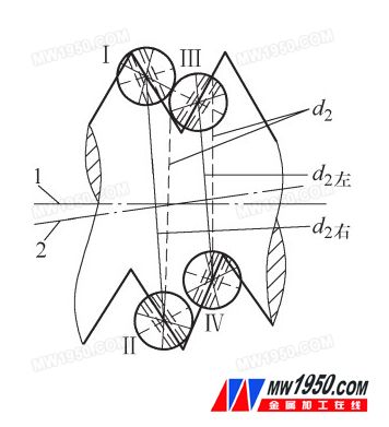
Figure 2 Measurement of the diameter of the thread
1. Thread axis 2. Measuring axis
When measuring, as shown in Figure 2, the dotted line of the angle of 60° in the eyepiece reticle is first overlapped with one side of the thread image (using the pressure line method), and the intersection point is roughly at the midpoint of the side. . In the position I in the figure, note the reading I on the lateral micrometer (the longitudinal micrometer does not move); rotate the lateral micrometer so that the corresponding side of the other side coincides with the same dotted line on the reticle Pay attention to the adjustment of the tilting direction of the column to ensure that the shape of the tooth is clear. As shown in Figure II, position II, record the horizontal micrometer reading II horizontal. The difference between the two readings - II horizontal - I horizontal - is the initial measurement. Due to the installation error of the thread to be tested, the thread axis does not coincide with the longitudinal rail direction (measurement axis) of the table, ie its axis cannot be absolutely perpendicular to the transverse rail. In order to eliminate the influence of such installation error on the measurement results, in the actual measurement, the median diameter of the adjacent (reverse) tooth surface (the amount of III to IV in the figure) should also be measured, and then the average value is taken. Is the median diameter of this thread.
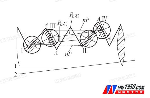
(2) The measurement of the pitch P of the external thread is measured by the image method as shown in Fig. 3. First, the dotted line of the angle of 60° on the eyepiece reticle is coincident with one side of the thread (pressure line method), and The intersection point is roughly at the midpoint of the side, as shown in Figure 6, where I read the longitudinal micrometer reading I longitudinal (the lateral micrometer does not move); rotate the longitudinal micrometer to move the thread image through n After the pitch (n can take 3 to 6 teeth according to the length of the threaded screw), so that the same side of the other tooth coincides with the dotted line on the same side of the reticle, and the position of II in Fig. 6 is recorded. The reading of the microprocessor is vertical, and the difference between the two readings is -II longitudinal - I longitudinal - that is, the pitch P n of the n teeth of this thread is left. Generally, the maximum pitch cumulative error ΔP n of the thread pair within any twist length should be measured. In the same way, in order to eliminate the influence of the screw mounting error, the actual pitch (III to IV) position of the other (reverse) tooth surface should also be measured, and then the average value is n teeth. Actual pitch.

Figure 3 Thread diameter measurement
1. Thread axis 2. Measuring axis
3. Measurement of the external thread half angle a/2
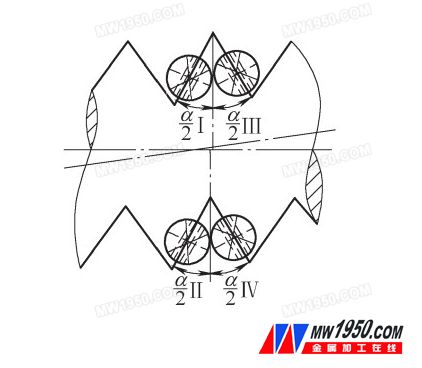
When measuring the half angle of the tooth shape by the image method, firstly divide the dotted line of the angle of 60° on the reticle to coincide with the side of the profile of the tooth profile to be measured, and the gap line method can be used for the measurement, and the intersection point is substantially on the side. At the midpoint, as shown in Figure 4, record the angle reading, the angle reading in the eyepiece is a/2I (ie, the left half angle); adjust the vertical and horizontal micrometers and the reticle to make the other side of the screw The edge coincides with the dotted line on the above reticle, and the position of II in Fig. 4, the angle reading a/2II (ie, the right half angle) is recorded. Pay attention to the correct orientation of the column when measuring, and ensure that the shape of the tooth is clear. Similarly, if the thread axis is inconsistent with the measurement axis, the front and back flank angles formed by the same spiral surface will be unequal. In order to eliminate the influence of the installation error, the left and right half angles of the other side are measured. III, IV position, the right half is a/2III, the left half is a/2IV. Finally, the measured average of a/2 is calculated comprehensively.

Figure 4 Measurement of thread half angle
1. Thread axis 2. Measuring axis
4. Conclusion
The measurement principle of the tool microscope and the measurement method of the external thread parameters are introduced. Some details of the operation need to be paid attention to during the measurement process, such as burrs and scars on the surface of the workpiece, correct installation of the workpiece to be tested, and tilting direction of the microscope column. Factors such as the focusing order of the eyepiece and the objective lens may cause the accuracy of the measurement result to be greatly reduced if temporarily neglected.
Pvc Roof Tiles,Plastic Roof Tiles,Synthetic Roof Tiles,Synthetic Glazed Roof Tile
Shandong Gaoxin Chemical Co.,Ltd , http://www.gaoxinchem.com