Intermediate relay wiring method Intermediate relay function and working principle
I think that people will have more or less exposure to electricity in their lives, especially those who work on circuits. Do you know if you have heard of relays? The intermediate relay is a product used in the relay protection and automatic control system to increase the number and capacity of contacts and it is used to transmit intermediate signals in the control circuit. However, you may not know much about intermediate relay wiring methods. Don't worry, if you have this need, you may wish to follow me to understand the relevant knowledge of the middle relay connection .
What is an intermediate relay
According to the role of the relay in the protection circuit, the relay can be divided into start relay, measurement relay, time relay, signal relay, outlet relay and intermediate relay.
The structure and principle of the intermediate relay is basically the same as that of the AC contactor. The main difference with the contactor is that the main contact of the contactor can pass a large current, while the contact of the intermediate relay can only pass a small current. Therefore, it can only be used in control circuits. It is generally without a main contact because the overload capacity is relatively small. Therefore, all of it uses auxiliary contacts and the number is relatively large. The new national standard defines K as the intermediate relay and KA as the old national standard. It is usually a DC power supply. A few use AC power.
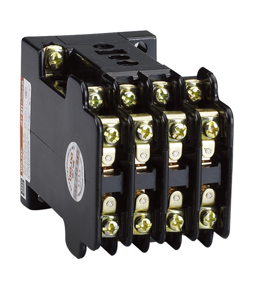
Intermediate relay structure
1. The coil is mounted on a "U" shaped magnetizer with a movable armature above it and two rows of contact springs on both sides of the magnetizer. In the non-actuated state, the contact spring lifts the armature upwards to maintain a certain gap between the armature and the magnetizer. When the electromagnetic torque between air gaps exceeds the reaction torque, the armature is attracted to the guide magnet, and at the same time, the armature presses the contact spring to close the normally closed contact and close the normally open contact to complete the relay operation. When the electromagnetic torque is reduced to a certain value, due to the reaction torque of the contact spring, the contact point and the armature return to the initial position, ready for the next work.
2. The "U"-shaped magnetic conductor of this relay adopts a double core structure, that is, coils can be installed on both side columns. For the DZY, DZL, and DZJ models, only one coil is mounted, and for the DZB, DZS, and DZK models, the other core can be equipped with a holding coil or a delay damping plate as required. Thus, a universal magnet is used for relays of different coil types.
3. The principle of the intermediate relay is the same as the AC contactor, which consists of a fixed iron core, a moving iron core, a spring, a moving contact, a static contact, a coil, a connection terminal and a housing.
Intermediate relay function
1 instead of a small contactor
The contacts of the intermediate relay have a certain load capacity. When the load capacity is relatively small, it can be used to replace the use of small contactors, such as electric roller shutters and control of some small appliances. This has the advantage that it not only serves the purpose of control, but also saves space and makes the control part of the appliance more sophisticated.
2. Increase the number of contacts
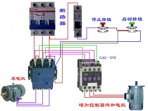
This is the most common use of intermediate relays. For example, in a circuit control system where one contactor contact needs to control multiple contactors or other components, an intermediate relay is added to the line.
3. Increase contact capacity
We know that although the contact capacity of the intermediate relay is not very large, it also has a certain load carrying capacity. At the same time, the current required for its driving is very small. Therefore, an intermediate relay can be used to expand the contact capacity. For example, it is generally impossible to directly use the output of a sensor switch or a transistor to control an electrical component with a relatively large load. Instead, intermediate relays are used in the control circuit to control other loads through the intermediate relays to achieve the purpose of expanding the control capacity.
Intermediate relay working principle
The coil of the intermediate relay is mounted on a u-shaped magnetic conductor, and an armature is arranged on the magnet. The two ends of the magnet are provided with two rows of contacts. The armature is lifted up in the non-moving state to make the armature and the magnetic conductor. Maintaining a certain gap, when the electromagnetic torque between the air gap exceeds the reaction torque, the armature is attracted to the guide magnet, and the armature presses the contact spring to close the normally closed contact and close the normally open contact. You have completed the signal. transfer.
Intermediate relay selection
Look at the current parameters of the contactor coil when working, and see the current parameters that the intermediate relay contacts can carry. Our company generally uses Omron MY2N-J (base PYF08AE), the contact carrying current is 5A, the general can be used. Schneider's is also good, go to the official website to download some information to see more detailed.
Intermediate relay price
OMRON relays have MY2NJ, MY4NJ and many other models. Genuine price is very expensive, with Omron MY2N-CR-J MY2NJ-CR AC220V, the price is about 40 yuan a set.
Note: This price is for reference only! Due to geographical differences, of course, the price will be different. For more details on the prices, please refer to the local distributors!
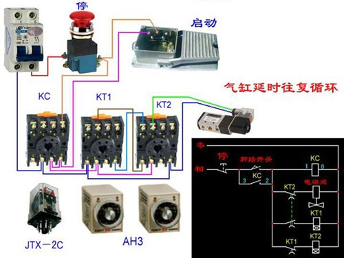
Intermediate relay wiring
Different relay wiring methods may have some differences. The following is a description of the wiring method of the eight wiring terminals.
5 and 6 are a pair of common terminals, 1 and 2 are a pair of normally closed contacts, and 3 and 4 are a pair of normally open contacts. When 7 and 8 are not energized, 5-6 and 1-2 are switched on, and after power-on, 1-2 will be disconnected, and 5-6 will be continued, and 3-4 will be connected.
The general intermediate relay is a double-pole double-throw switch, and the 7-8 terminal is connected to the internal coil. When it is used, a freewheeling diode is connected in parallel. The polarity when the diode is connected is marked opposite to the relay terminal (8+ then the negative terminal of the diode, The positive electrode of the 7-connector diode), when the predetermined value is reached, the relay will work to drive the drive circuit to be disconnected. That moment will produce a very high current due to the self-inductance voltage, and this current will flow through the freewheeling diode. Without passing through the circuit, the components in the circuit are protected.
Intermediate relay selection
1. Consider the contact capacity: that is, the maximum voltage (rated voltage), current that is allowed to pass;
2. Select the number and type of contacts according to the requirements;
3. The voltage level of the electromagnetic coil is equal to the power supply voltage of the control circuit;
4. The operating frequency of the relay;
5. The salary system of the relay system;
6. The use of the environment, climate and other objective factors;
Editor's summary: The above is the intermediate relay wiring method intermediate relay function and working principle of the relevant knowledge, hope to help to meet the needs of friends! For more information, please continue to pay attention to our website, follow-up will show more exciting content. You can also buy your favorite products on Qijia Mall.
High Current Relay Low Voltage Relay Safety Relay Relay Switch Three Phase Solid State Relay Intermediate Relay Wiring
Makeup Brush Kit,Makeup Brush Set,Soft Makeup Brush Set,Professional Makeup Brush Set
YANGJIANG TRI-WIN INDUSTRY & TRADE CO.,LTD , https://www.triwintableware.com