Analysis of the coordinate conversion macro program of the icosahedron gantry machine
In recent years, the rapid development of industries such as nuclear power, wind energy, and railway systems has brought new challenges. The processing efficiency and accuracy of large structural components have become critical bottlenecks. To address this, the pentahedron machining center has emerged as a key solution. This machine allows for the machining of five faces of a workpiece in a single setup, eliminating the need for multiple setups and improving both precision and productivity. It combines the functions of vertical and horizontal machining centers, ensuring high positioning accuracy and stable machining performance.
Traditional methods often require multiple coordinate system alignments, which are time-consuming and labor-intensive. However, with the implementation of the pentahedron vertical coordinate conversion macro program, the process becomes much simpler. The program enables one-time coordinate system setup, automatically performing all necessary transformations through the internal control system. Programmers no longer need to account for variations in the vertical head size, as they can use the tool tip point for programming. This results in a more straightforward, easy-to-understand, and easily modifiable program, fully demonstrating the high efficiency and precision of the pentahedron machining center.
This article introduces the principle and method of the vertical coordinate conversion macro program based on the FANUC numerical control system. The pentahedron machining center typically features two heads, with the vertical head capable of precise indexing at 15° intervals via the spindle-driven ratchet mechanism.
**1. Calibration of the Vertical Head Geometry on a Versatile Machine Tool**
Accurate calibration is essential for correct coordinate transformation. Due to differences in the geometric dimensions of the vertical head and assembly errors between the head and its center, measuring tools such as gauges, check rods, and gauge blocks are used for calibration. The dimensions involved in the calibration are shown in Figure 1.
Figure 1 illustrates several key measurements: #501 represents the distance from the main spindle's end face to its center axis (see Figure 1a), #502 is the same measurement but for the vertical head (also shown in Figure 1a), and #503 indicates the misalignment between the center axes of the vertical and horizontal heads (as seen in Figure 1b).
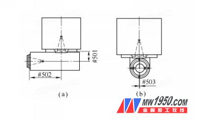
*Figure 1: Vertical and horizontal calibration dimensions*
**2. Algorithm for Compensation in the Icosahedron Machine Coordinate Transformation Macro Program**
To facilitate the macro program’s calculations, we built a mathematical model by projecting the vertical and horizontal heads onto the XY and ZX planes (see Figure 2). This model helps convert spatial vectors into X, Y, and Z directions, making it easier to implement compensation within the macro program.
Point O represents the origin of the coordinate system for the vertical head, and angle C is the angle between the head and the positive X-axis direction.
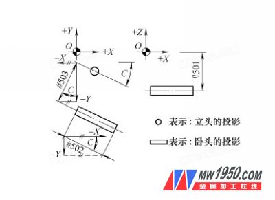
*Figure 2: Mathematical model of the head and head on the projection surface*
Using trigonometric functions, we calculate the vector values of the geometric differences between the vertical and horizontal heads in the X, Y, and Z directions:
- **X-direction component:** #502 × cos(C) - #503 × sin(C)
- **Y-direction component:** #503 × cos(C) - #502 × sin(C)
- **Z-direction component:** #501
**3. Coordinate Conversion Macro Programming for the Pentahedron Machining Center**
To improve program readability and ease of modification, we rotate the workpiece coordinate system so that the machined surface aligns with the "XY" plane. This approach simplifies programming and ensures consistency across different machining operations.
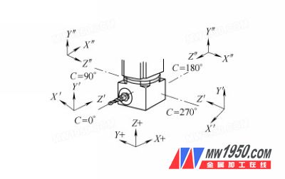
*Figure 3: Schematic diagram of the rotation of the horizontal machining coordinate system*
Based on the space angle model of the vertical head, the FANUC system commands "G52" (coordinate translation) and "G68" (coordinate rotation) are used to create the coordinate conversion macro program for the pentahedron machining center. To make it more user-friendly, we define a custom G-code "G333" for calling the program. The format is as follows:
**G333 X___ Y___ Z___**
*(Eccentricity compensation, coordinate translation, and rotation are effective.)*
**4. Example of Processing Using the Pentahedron Vertical Coordinate Conversion Macro Program**
The workpiece is processed as shown in Figure 4. The steps include:
1. Setting up the workpiece coordinate system "G55" at the center of the upper plane.
2. Rotating the head to 60°.
3. Using the macro program to translate and rotate the coordinate system to the new origin, then drilling a hole at the new origin with a depth of 30 mm.
```plaintext
G40 G69 G49 G55 (Cancel all compensations)
T1 M6 (Tool change)
G00 C60 (Rotate head to 60°)
S1000 M3 (Spindle forward rotation)
G333 X100. Y-50. Z-100. (Call macro program, shift to new origin)
G00 Z500. (Move to safe Z position)
X0. Y0. (Move to new coordinate origin)
Z100. (Safety Z position)
G98 G81 Z-30. R5. F100 (Drill deep hole)
G80 (Cancel fixed cycle)
G00 Z500. (Return to safe location)
G334 (Cancel tool offset, coordinate conversion, head compensation)
M5 (Spindle stop)
M30 (End of program)
```
**5. Conclusion**
The application of the pentahedron coordinate conversion macro program significantly simplifies the machining process, compensates for eccentricity errors, improves machining accuracy, and enhances overall efficiency. It fully leverages the multi-face machining capabilities of the pentahedron machining center, bringing substantial economic benefits to the company.
Deep Groove Ball Bearing,Single Row Deep Groove Ball Bearing,Stainless Steel Deep Groove Ball Bearing,Micro Deep Groove Ball Bearing
Shanghai Yi Kai Cheng bearing Co., LTD , https://www.ykchbearing.com