Design and manufacture of four oblique bending injection molds (2)
Option 3: Pneumatic or hydraulic core pulling mechanism.
This core-pulling mechanism greatly simplifies the core-pulling mechanism, and the mold requires only an additional air pressure or hydraulic system. However, here is the oblique core (60° angle to the mold opening direction), which will occupy a large mold space. Although the mold manufacturing difficulty is reduced, the mold volume and the mold material cost and processing cost are increased. Not ideal.
Option 4: Lever + crank slider oblique side core pulling mechanism.
In order to make the mold more compact, easier to manufacture, easier to repair, reduce mold material cost and processing cost, I specially designed the lever + crank slider oblique side core pulling mechanism, as shown in Figure 3. The core pulling mechanism is composed of a slanting core 11, a slanting slider 10, a connecting rod 9, a lock nut 8, a swinging rod 7 (that is, a lever and a crank), a locking block 23 and the like. The crank slider mechanism The action of pulling the oblique core and its reset (injection molding) is completed. The lock nut 8 can be conveniently adjusted on the position of the pull rod 5. When the mold is assembled, the oblique side core is placed at the position of the core, and then the position of the lock nut is finely adjusted so that the lock nut is clamped. Just tighten the swing lever (the swing lever uses the principle of lever to provide the core pulling force when the oblique side core is pulled), and the oblique core 11 is reset. When the mold is opened, the swing rod is disengaged from the lock nut, and the oblique side core returns to the free state of the core, and the core pulling operation is completed. Therefore, the lock nut plays the dual role of locking the inclined slider and adjusting the core distance, and better solves the problems encountered by the above three solutions.
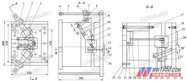
Figure 3 mold assembly sketch
1. swing rod seat 2. middle guide slide 3. oblique guide slide 4. double nut 5. draw rod
8. Lock nut 9. Connecting rod 10. Oblique slide 11. Inclined side core 12. Oblique side core fixing screw 13. Locating ring 14. Sprue sleeve 15. Fixed model cavity
16. Dynamic model cavity 17. Base plate long screw 18. Panel screw 19. Core 20. Middle side core 21. Panel 22. Fixed plate (A plate) 23. Lock block
24. Middle slider 25. Oblique guide post 26. Moving plate (B plate) 27. Square iron 28. Top point 29. Upper needle plate 30. Lower needle plate 31. Needle plate screw 32. Base plate 33.
2. Manufacturing of core pulling mechanism
There are 3 sets and two kinds of core pulling mechanisms in the injection mold. Most of the parts in the inclined guide column core pulling mechanism and the crank slider core pulling mechanism are simple in shape and low in precision, so the processing method is simple and easy to manufacture. The moving parts of the core pulling mechanism and the moving mold cavity are all mounted on the moving template 26, and the shape of the movable template is relatively complicated, as shown in FIG. 4, the manufacturing process is as follows:
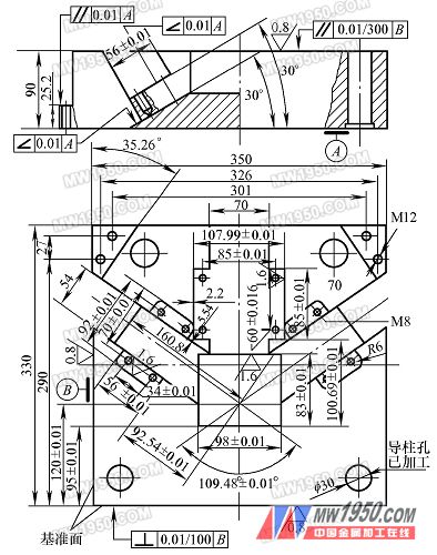
Figure 4 moving template (B board) parts drawing
Previous page next page
Rear Bumper Mould,Rear Bumper Molding,Rear Bumper Moulding,Car Bumper Molding
Taizhou ANO MOULD CO.,LTD , https://www.ainomould.com